HOTLINE: +91 851-114-2701
Hydraulic Press Brake Machine
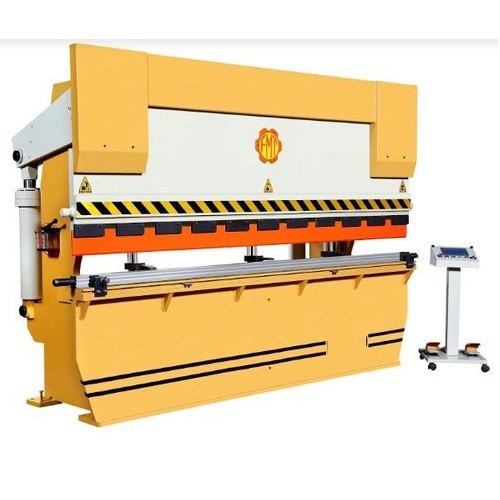
A hydraulic press brake is a machine tool used for bending sheet metal and plate material. It works by clamping the workpiece between a punch and a die, with the force generated by hydraulic cylinders. Press brakes are essential for creating precise bends, angles, and forms in metal fabrication.
Types of hydraulic press brake machine
Bent Metal Components: Brackets, enclosures, cabinets, channels, angles, Z-sections, and complex folded parts for various industries.
Ducting and HVAC Components: Custom-bent parts for air handling systems.
Architectural Metalwork: Facade panels, railing components.
Automotive and Aerospace Parts: Chassis components, panels, structural members.
Appliance Housings: Bent metal parts for washing machines, refrigerators, etc.
Applications in Various Industries
Applications:
Sheet metal fabrication shops, automotive manufacturing, aerospace industry, HVAC manufacturing, construction (e.g., flashing, roofing components), appliance manufacturing, electronics enclosures, heavy machinery manufacturing.
Technology:
Hydraulic System: Consists of pumps, cylinders, valves, and fluid that generate and control the bending force. Offers advantages of consistent pressure throughout the stroke and overload protection.
CNC (Computer Numerical Control): Modern press brakes are typically CNC controlled. The CNC system precisely controls ram position (Y-axis), back gauge position (X, R, Z1, Z2 axes for depth, height, and lateral movement), and sometimes crowning.
Back Gauge Systems: Motorized and programmable back gauges provide precise positioning of the sheet metal for accurate bend line placement. Multi-axis back gauges allow for complex part geometry.
Crowning Systems: Compensate for deflection of the press brake bed during bending, ensuring a consistent bend angle across the entire length of the workpiece. Can be manual, hydraulic, or mechanical.
Tooling: A wide variety of punches (upper tools) and dies (lower tools) are available for different bend angles, radii, and material thicknesses. Quick-change tooling systems enhance efficiency.
Safety Features: Light curtains, laser safety systems, and dual palm buttons ensure operator safety.
Angle Measurement Systems: Lasers or sensors can measure the actual bend angle in real-time and provide feedback to the CNC for automatic correction.
Offline Programming Software: Allows programming of bending sequences and collision detection without occupying the machine.
Material Selection Considerations
For Machine Components:
For Workpiece Materials (Being Bent):
FAQ's